rhoadley.net music research software blogs
aru seminars m&t critski focm1a cmc circuit bending mic2b sensor technology comp 3 sonic art major project
youtube vimeo facebook
Sensor Technology Tasks
Arduino, MaxMSP and SuperCollider
| Task 11 | Connecting the Arduino, MaxMSP and SuperCollider | Set: w9 | Due: w13 | Weighting: logbook (50%) | Courses: stech |
| Prev Task: Vibrating a piezo | Next Task: Mapping | ||||
| Task Summary | All cbhh tasks | ||||
To cover:
- Using the Arduino with MaxMSP
- Using the Arduino with SuperCollider
- NB you may need to quit MaxMSP or SC before you can upload programmes to the Arduino
- Making Things Talk
- Using breadboards with the Arduino
- Using a flex sensor
Connecting Arduino and Max
- Max (5+) patch: save this with the extension 'maxpat'.
- Arduino2Max_Basic.maxpat - a simple patch controlling a Max5 patch with an Arduino. Includes some explanatory detail.
- Max For Dummmies also works with Arduino 1.6.5 and Arduino Uno.
Please see here for the latest versions of these patches, as well as other methods of communicating.
Follow the below link for more information on ASCII translations.
Connecting Arduino and Supercollider
NB In order to use it you must install the Arduino quark. Evaluate the following to see if it's already there:
Quarks.gui;
If not, you should be able to install it with an internet connection and the following:
Quarks.update("arduino");
Quarks.install("arduino");
After installation you'll need to recompile the Library (command-k).
See the Quarks helpfile for more information.
- SuperCollider patches - these contain basic templates for controlling synths, etc:
- arduino_to_SC01.scd - a simple patch controlling a SuperCollider patch with an Arduino.
- arduino_to_SC01.scd - another example using SMS: beware!
- ArduinoToMaxArd.pde - the Arduino code.
- You might also like to check this class: http://rhoadley.net/courses/tech_resources/stech/tasks/ArduinoToSC/ArduinoByte.scd which should enable you to do the same as ArduinoSMS in one direction. Here's an example file.
Really Simple SC Example
Arduino Code
/*
  Analog input

 reads an analog input on analog in 0, prints the value out.

 created 24 March 2006
 by Tom Igoe
 */

int analogValue = 0;    // variable to hold the analog value

void setup() {
  // open the serial port at 115200 bps:
  Serial.begin(115200);
}

void loop() {
  // read the analog input on pin 0:
  analogValue = analogRead(0);

  Serial.println(analogValue);       // print as an ASCII-encoded decimal

  // delay 10 milliseconds before the next reading:
  delay(10);
}
SC Code
// change the serial port identifier...
p = ArduinoSMS("/dev/tty.usbserial-A9007KNG", 115200);
p.action = { |... msg| msg.postln };
p.close; // close just the port you've just opened
SerialPort.closeAll; // close all ports.
MaxMSP
Use the patch above.
Arduino Code for Sending more than one value...
Then you can read the results as an array in SC. In Max you should see two values on Analog ins 1 and 3 - the second value is the comma!
int analogValue0 = 0;    // variable to hold the analog value
int analogValue1 = 0;

void setup() {
  Serial.begin(115200);
}

void loop() {
  analogValue0 = analogRead(0);
  analogValue1 = analogRead(1);

  Serial.print(analogValue0);
  Serial.print(", ");
  Serial.println(analogValue1);

  delay(10);
}
Digital signals
Buttons
For Max use the Arduino for Dummies patch
/*
  Button

 Turns on and off a light emitting diode(LED) connected to digital
 pin 13, when pressing a pushbuttons attached to digital pins 2, 3 and/or 4.
 Also sends a message.

 This is primarily for use with SC and for demonstrating with Arduino itself.  For examples of this with Max use the Max for Dummies patch.:
 http://playground.arduino.cc/Interfacing/MaxMSP#ArduinoMax_InOut_forDummies

 The circuit:
 * LED attached from pin 13 to ground
 * pushbutton attached to pin 2 from +5V
 * 10K resistor attached to pin 2 from ground

 * Note: on most Arduinos there is already an LED on the board
 attached to pin 13.


 created 2005
 by DojoDave
 modified 28 Oct 2010
 by Tom Igoe
 modified 13 Oct 2012
 by rhoadley.net

 This example code is in the public domain.
 See below for wiring
 http://www.arduino.cc/en/Tutorial/Button
 */

// constants won't change. They're used here to
// set pin numbers:
const int buttonPin2 = 2;     // the number of the pushbutton pin
const int buttonPin3 = 3;
const int buttonPin4 = 4;
const int ledPin =  13;      // the number of the LED pin

// variables will change:
int buttonState2 = 0;         // variable for reading the pushbutton status
int buttonState3 = 0;
int buttonState4 = 0;
int del = 20;   // allow some time for the pins to adjust
                // NB if you're using bluetooth, this value needs to be higher 10ms crashes blueSMIRF).


void setup() {
  Serial.begin(115200); // needs to be this to work with bluesmirf
  // initialize the LED pin as an output:
  pinMode(ledPin, OUTPUT);
  // initialize the pushbutton pin as an input:
  pinMode(buttonPin2, INPUT);
  pinMode(buttonPin3, INPUT);
  pinMode(buttonPin4, INPUT);
}

void loop(){
  // read the state of the pushbutton value:
  buttonState2 = digitalRead(buttonPin2);
  buttonState3 = digitalRead(buttonPin3);
  buttonState4 = digitalRead(buttonPin4);

  // check if the pushbutton is pressed.
  // if it is, the buttonState is HIGH:
  if (buttonState2 == HIGH) {
    // turn LED on:
    digitalWrite(ledPin, HIGH);
    Serial.print("pin 2:");
    Serial.println("on!");
  }
  else if (buttonState3 == HIGH) {
    // turn LED on:
    digitalWrite(ledPin, HIGH);
    Serial.print("pin 3:");
    Serial.println("on!");
  }
  else if (buttonState4 == HIGH) {
    // turn LED on:
    digitalWrite(ledPin, HIGH);
  }
  else {
    // turn LED off:
    digitalWrite(ledPin, LOW);
  }
  delay(del);
}
Button with a more sensible message
NB 121013 this code seems to require the USB cord to be removed before it will
work with MaxMSP.  It works fine with SC (and ArduinoSMS quark).  It works with the basic Max Patch linked to above.


/*
  Button with a more sensible message

 Turns on and off a light emitting diode(LED) connected to digital
 pin 13, when pressing a pushbutton attached to digital pin 2.
 Also sends a message.
 Buttons 2 sends a more sensible message which can be read with the basic Max Patch.


 The circuit:
 * LED attached from pin 13 to ground
 * pushbutton attached to pin 2 from +5V
 * 10K resistor attached to pin 2 from ground

 * Note: on most Arduinos there is already an LED on the board
 attached to pin 13.


 created 2005
 by DojoDave
 modified 28 Oct 2010
 by Tom Igoe
 modified 13 Oct 2012
 by rhoadley.net

 This example code is in the public domain.
 See below for wiring
 http://www.arduino.cc/en/Tutorial/Button
 */

// constants won't change. They're used here to
// set pin numbers:
const int buttonPin2 = 2;     // the number of the pushbutton pin
const int ledPin =  13;      // the number of the LED pin

// variables will change:
int buttonState2 = 0;         // variable for reading the pushbutton status
int del = 20;   // allow some time for the pins to adjust
                // NB if you're using bluetooth, this value needs to be higher 10ms crashes blueSMIRF).


void setup() {
  Serial.begin(115200); // needs to be this to work with bluesmirf
  // initialize the LED pin as an output:
  pinMode(ledPin, OUTPUT);
  // initialize the pushbutton pin as an input:
  pinMode(buttonPin2, INPUT);
}

void loop(){
  // read the state of the pushbutton value:
  buttonState2 = digitalRead(buttonPin2);

  // check if the pushbutton is pressed.
  // if it is, the buttonState is HIGH:
  if (buttonState2 == HIGH) {
    // turn LED on:
    digitalWrite(ledPin, HIGH);
    Serial.print("2 ");
    Serial.println("1");
  }
  else {
    // turn LED off:
    digitalWrite(ledPin, LOW);
    Serial.print("2 ");
    Serial.println("0");
  }
  delay(del);
}
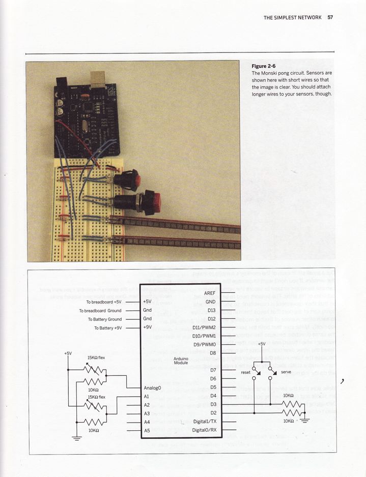
Arduino and Breadboards
If you attempted to use two controllers with one board it will have occurred to you that you don't really have enough holes. If this is the case, then you'll want to use a breadboard.
Sending messages TO the Arduino
Try using:
http://playground.arduino.cc/Code/CmdMessenger
Old style - Simple Message System - sending messages TO the Arduino
NB There are some developments with this. Hold the phones... SMS does not work with Arduino 1+. Maybe look at Firmata and SCPyduino??? However SMS does still work with Arduino 0023 and below...
For full functionality, but you'll need to uncompress the following file for Arduino 1 and above:
http://rhoadley.net/courses/tech_resources/stech/tasks/SimpleMessageSystemArd1.zip
Or the following file for Arduino 0023 and below:
http://rhoadley.net/courses/tech_resources/stech/tasks/SimpleMessageSystem.zip
...and put the uncompressed directory into Arduino/Contents/Resources/Java/libraries/
and restart Arduino. Then, in SC you can use this:
http://rhoadley.net/courses/tech_resources/stech/tasks/ArduinoToSC/Arduino.scd
to test. Examples in MaxMSP, PD and Processing are included in the library.
See the next task for this functionality, but you'll need to uncompress the following file: http://rhoadley.net/courses/tech_resources/stech/tasks/SimpleMessageSystem.zip ...and put it into Arduino/Contents/Resources/Java/libraries/ and restart Arduino
|
You might also be interested in:
- Other boards
The Projects
The projects and tasks are designed to help you through the various courses and materials that you'll have to deal with, and also to provide an active and practical element to what could otherwise become a rather dry and technical exercise. Tasks are small exercises - you may be asked to complete one or two per week. Projects are larger and carry a higher percentage of the mark. We will undertake two, three, four or more projects and tasks. The final project is usually an individual choice project, and will be worth significantly more than the others in terms of percentages in your portfolio. We will usually try to set aside a time to perform the projects in a public setting.